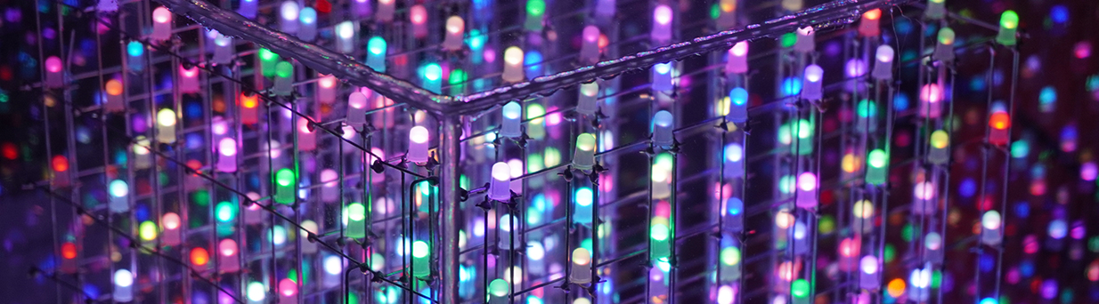
8x8x8 LED RGB CUBE - Part 3
This project we are going to build an 8x8x8 LED 5mm rgb cube
On this part 3 we are going to finish to assemble the led cube and run some tests. Now that we have our pcb printed boards we can start adding the components.
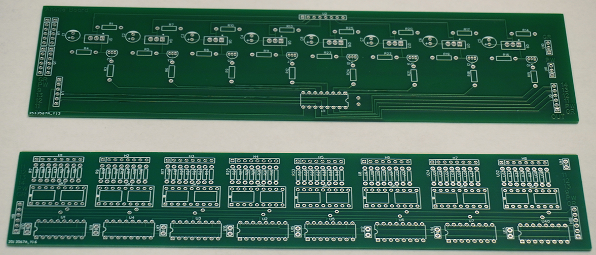
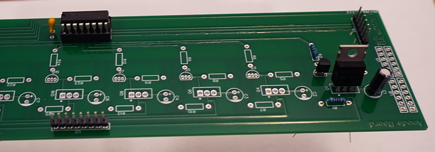
First I will start with the anode board, this board will take 8-100ohm resistor, 16-1000ohm resistor, 8-IRF9530 MOSFET P, 8-2N3904 NPN transistor, 8-100uF electrolytic capacitor, 1-0.1uF ceramic capacitor, 1-74HC595 IC shift register, 1-Pressed DIP 2.54mm pitch IC socket 16 pins and a few 2.54mm male pin headers.
The connections on these boards are very close to each other, so you have to be very careful to not bridge them. Next will be the cathode boards which will be three of them red, green and blue. Each board will take 64-100ohm resistors(150ohm for the red board), 8-74HC595 IC shift register, 8-ULN 2803 shift register, 8-0.1uF ceramic capacitor, 8-Pressed DIP 2.54mm pitch IC socket 16 pins, 8-Pressed DIP 2.54mm pitch IC socket 18 pins and few 2.54mm male pin headers.
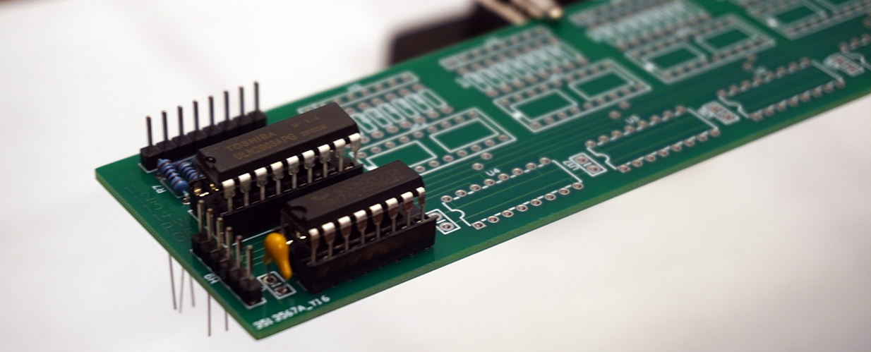
For the cathode red board I used a set of one 100ohm resistor and one 56ohm resistor connected in series because I didn't have the 150ohm resistor in hand. It was a little more work but it worked well due to the tie space. After finished solder all the components I prepare the Arduino Mega with the jump cables needed. To start testing the cube I used the 5V from the Arduino Mega which later I would use a power supply to run the cube. You can not run the cube from the microcontroller power once you finished. The microcontroller and the cube each will have its own line of power from the power supply. At this point I connected all the boards and the Arduino Mega to the cube and I run the first test and there were a few things didn't go right. I checked the connections from the cube to the boards and found that I switched the pin 1 to the last one. But that was not the only problem, the led light up sequence still not right and some ghost leds light up also. After a quite few hours of checking for connections and found that everything was fine. But at this point the boards and microcontroller still loose at the bottom of the cube, once I secured them with hot glue the problems went away 95 percent. The led light up sequence was right and there was only one ghost led, the very first blue one. So I said I will figure this later because is not so major.
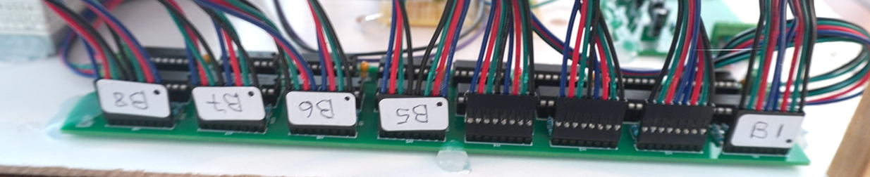
Blue cathode board, the black dot on the connector it means pin 1, which can be very confuse if you don't map yourself well.
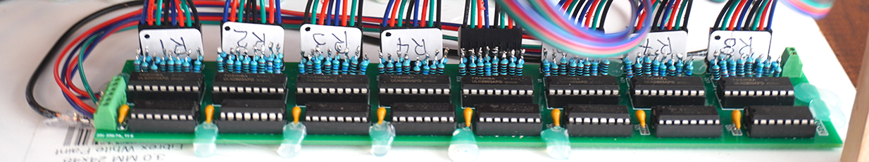
This is the red cathode board, notice the 100-56ohms resistors connect in series.
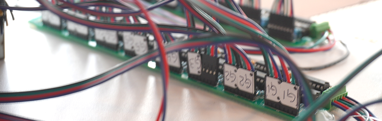
And the middle one which is the green cathode board, one thing I forgot to mention I used pcb block connectors for the boards, which is a lot than the male pin connectors. Remember when you are dealing with leds nothing can be loose around.
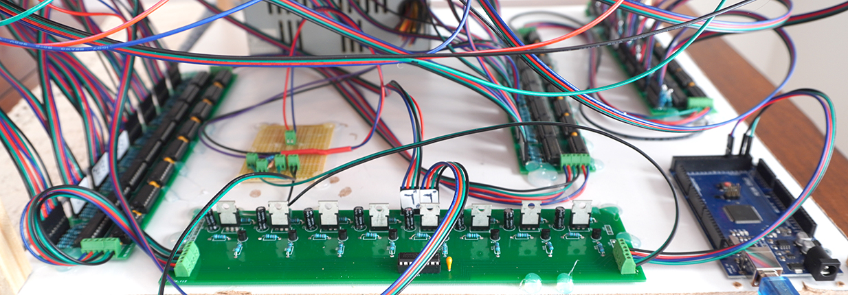
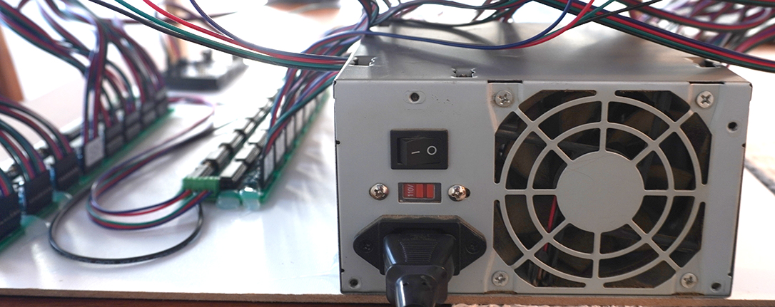
And finally the anode board which is the front one after the microcontroller, then blue board, green board and red board. This is the final setup before I build the box for it. At this point I still have that ghost led light up. After sometime searching online I found that the problem was the power. If I would power the cube and microcontroller from my computer usb the ghost led would appear. So I run a little test with my camera usb power supply and guess what? The ghost led was gone! So after I decided to run the cube with an old computer power supply that I had around.
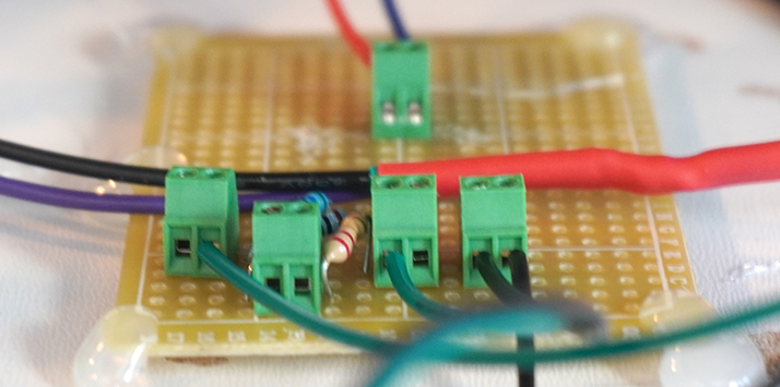
Bellow is a little board that I built for the power coming from the power supply and going to the anode board and the microcontroller. Notice I had to add some resistors on the anode board line other wise some other ghost would appear.
The Arduino Mega I powered through the USB cable which I stripped and solder an extension to feat the pcb block connector. There are other ways to power the Arduino, but the USB is the best because that is where the voltage reculator is. After that I was ready to run the first test.
So far it seems to be ok and its not showing any ghost led. Next I upload a sketch to the Arduino with some animations. In order to do that you need the Arduino IDE software which you can download for free online. I will be posting some tutorial in the near future about some animations that I did myself. The animations bellow are a combination of some of my and some that was available online, also the sketch is for the Arduino Mega which has different ports than the UNO..
CONCLUSION:
This cube was my third one that I built. The two first ones did not turn out like this one at all, I had made my own pcb boards and that was a lot solder plus a lot mistakes on wire connections. I say that a project like this is intermediate to advance. My very first cube was a 4x4x4 monochrome led. I learn a lot from that and I think is a good start if you are new on led cubes. I don't have any degree in electronics and what I know is by building projects like this and learn from the mistakes. This cube is not perfect, I still can see some ghost led, but by far this is the best one. If you have any question you can make through my youtube channel.