8x8x8 LED RGB CUBE - Part 2
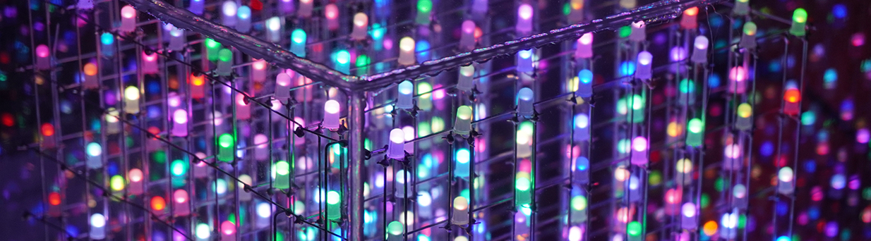
This project we are going to build an 8x8x8 LED 5mm rgb cube
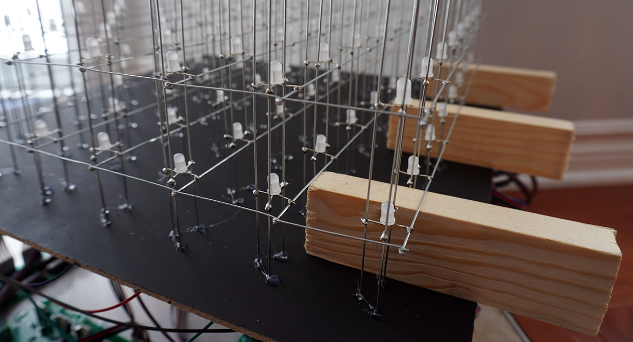
Continue with our LED rgb cube project, after I inserted the first slice I level with a few pieces of wood at the bottom of the slice and secure with a little hot glue like the sample bellow.
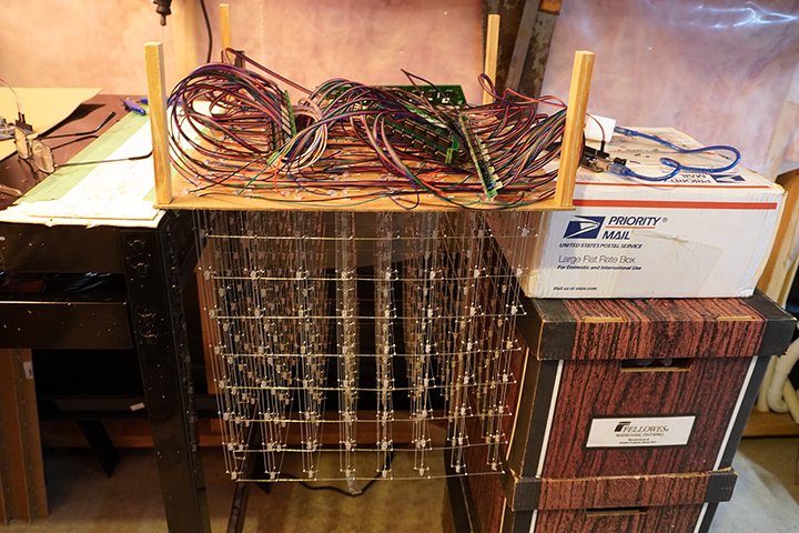
And to prevent the slices to go forward or backward I cut 16 pieces of the 20 gauge wire and solder on the side of the anode levels with the exact 2 inches apart. After done that all the eight slices the cube was pretty secure and reasonably straight. The next step the work is done under the cube, like trim all the leads, I left about one inch long so I could bend and apply more hot glue to secure the columns even more. The three wires from the columns RGB cathodes I used 22 gauge insulated wire. I got a 100ft. of this wire that came with a set of 4 wires together with the RGB colors and black. So two sets of this wire gave me one set of eight wires. This is the part that there are many different wires you can use like ribbon type etc. To work under the cube I flipped the cube using my work table and a few banking boxes.
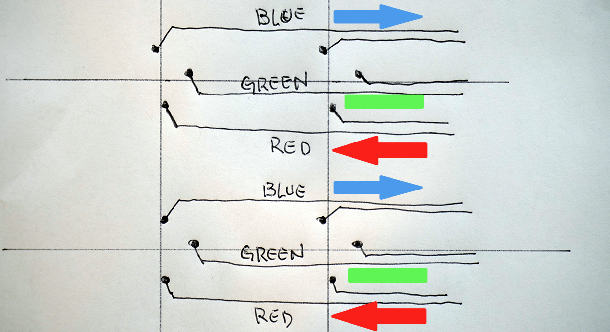
The way that I solder the wires on the columns was to leave the red and blue wires on the opposite directions and the green in the middle. So this way I was able to leave enough space around the circuit boards plus space for the microcontroller and the power supply.
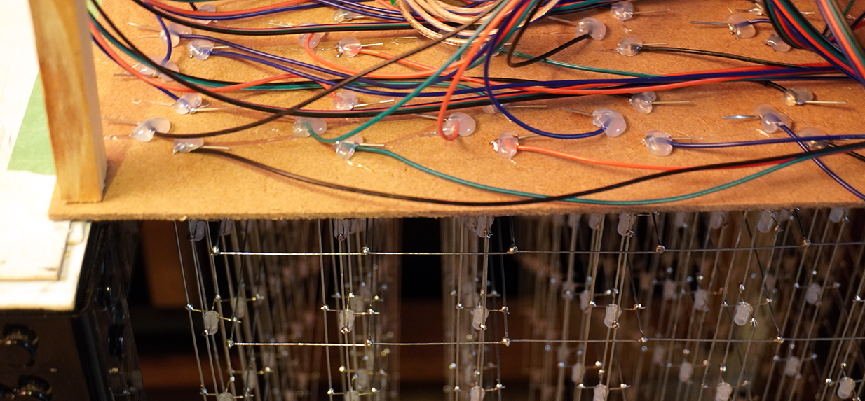
The processing of wire the cube is very important to pay a lot of attention, like which direction and what pin belongs to what color etc. Another very important thing is to secure every single connection because when you flip the cube back it can get loose and or vibration that would make the LEDs not act properly, LEDs are very sensitive to things like that. After I finished this process I started crimping the end of the wires to get ready the connectors for the circuit boards.
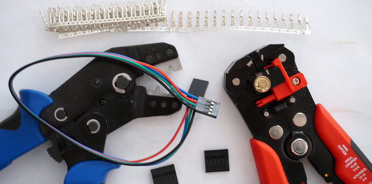
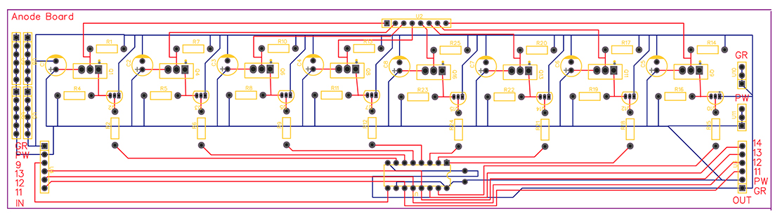
The main reason that I like to make my own wire connectors is because you get the exact size you need, it takes a little longer but it is worth. The next step is to work on the circuit boards which will be one for the Common Anode drive board and the other three Common Cathode drive board one for each color red, green and blue. The circuit boards I had printed at JLCPCB and the gerber files can be download here: Common Anode drive board - Common Cathode drive board . Having the pcb boards print like that it cuts down a lot of work and things that can go wrong like solder mistakes, plus is not expensive I believe under $50 you can get them. Bellow is a sample how the common anode board look like.
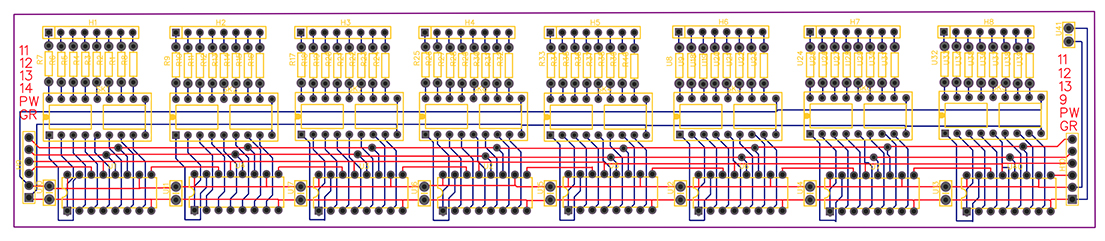
And the common cathode board which we need three of them one for each color.
On the next part 3 of this project we are going to connect the components to the pcb boards, connect all the boards to the cube and run our first test.