8x8x8 LED RGB CUBE - Part 1
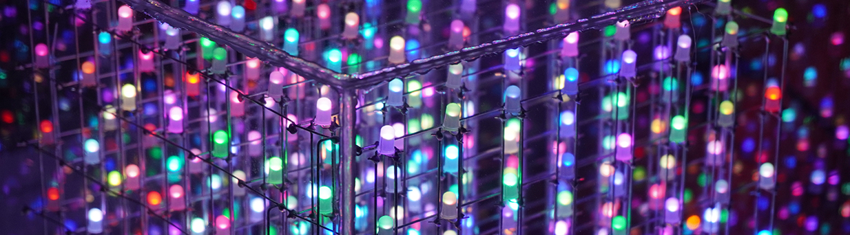
This project we are going to build an 8x8x8 LED 5mm rgb cube
Bellow is a list of material that we need to build the cube. The amount of material is exact what is going on the circuit boards and is a good idea the get extra of everything.
- 512 - LED 5mm RGB anode
- 25 - 74HC595 IC shift register
- 24 - ULN 2803 shift register
- 136 - 100 ohm resistor
- 64 - 150 ohm resistor
- 16 - 1 k ohm resistor
- 1 - 10 k ohm resistor
- 8 - IRF9530 MOSFET P
- 8 - 2N3904 NPN transistor
- 8 - 100uF electrolytic capacitor
- 25 - 0.1uF ceramic capacitor
- 100 ft. 22 AWG 4 pin RGB wire cord line(this is optional, other kind of wire works fine)
- 500 Female and Male pin connector terminal(this is optional, you can buy the wire with the connector)
- 200g 0.8mm solder wire
- 25 Pressed DIP 2.54mm pitch IC socket 16 pins
- 24 Pressed DIP 2.54mm pitch IC socket 18 pins
- 20 pieces 40 pins 2.54mm male pin headers
- 1 Arduino Mega 2560 R3 board ATmega2560 16U2
- 50 pieces block circuit connector
- 200 feet galvanized steel wire(Hillman is the best)
This list is pretty much what we need plus the printed circuit boards which I will talk more about later. As you may noticed on the list I like to make my own connections and crimping the wires. The reason is because I never found a ready wire the right length that I need. Also everything on the list you can find at Amazon or ebay.
This project initially I followed Kevin Darrah led cube, but with some modifications on the circuit boards. To sink the cathodes from the leds I choose to use the ULN 2803 shift register, which is eight Darlington transistors. This way cuts down the amount of work and soldering.
A sample bellow is how I build the cube itself. For this part there are many different ways to design a cube with the leds and the galvanized steel wire. My goal was to build eight vertical slice and each have eight rows and eight columns and 64 leds.
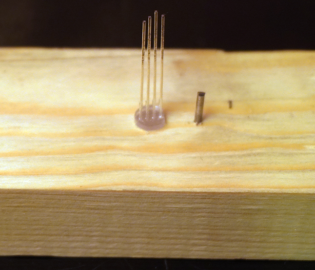
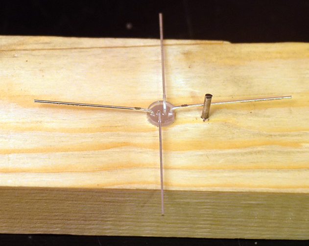
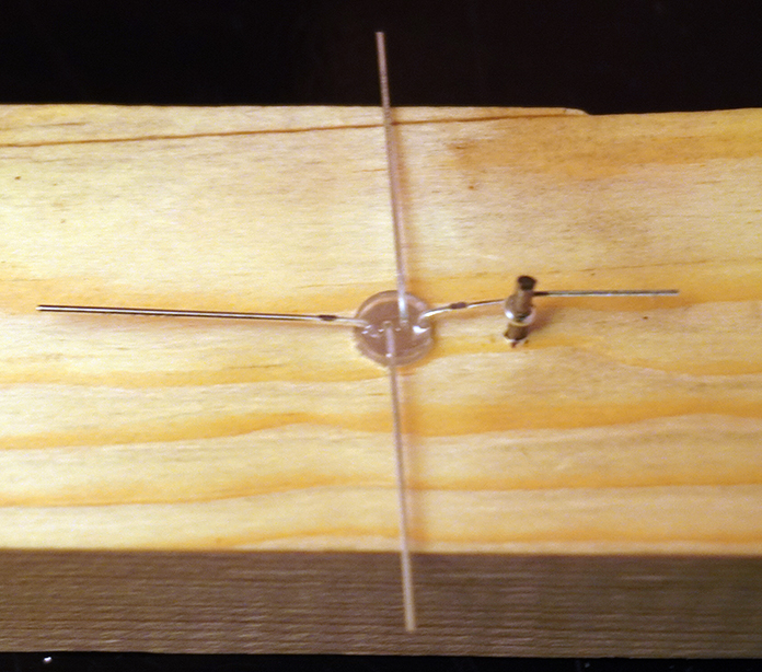
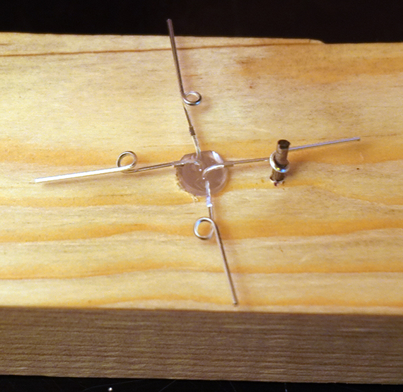
This is how I bent the leds to start building the slices. With the help of a piece of wood and a 5mm hole and a nail about 1/4 inch away from the hole.
Now you have that 512 times for each LED. Some people test each LED before the slices, I like to test them after I build the slices because is much faster and if there is an LED that is not working is quite easy to replace it. After I have the 512 LEDs ready to go. I made a rack from MDF board to support the slices with the LEDs and the space between the holes in my case is 2 inches depending what size the cube you want to be, see sample bellow.
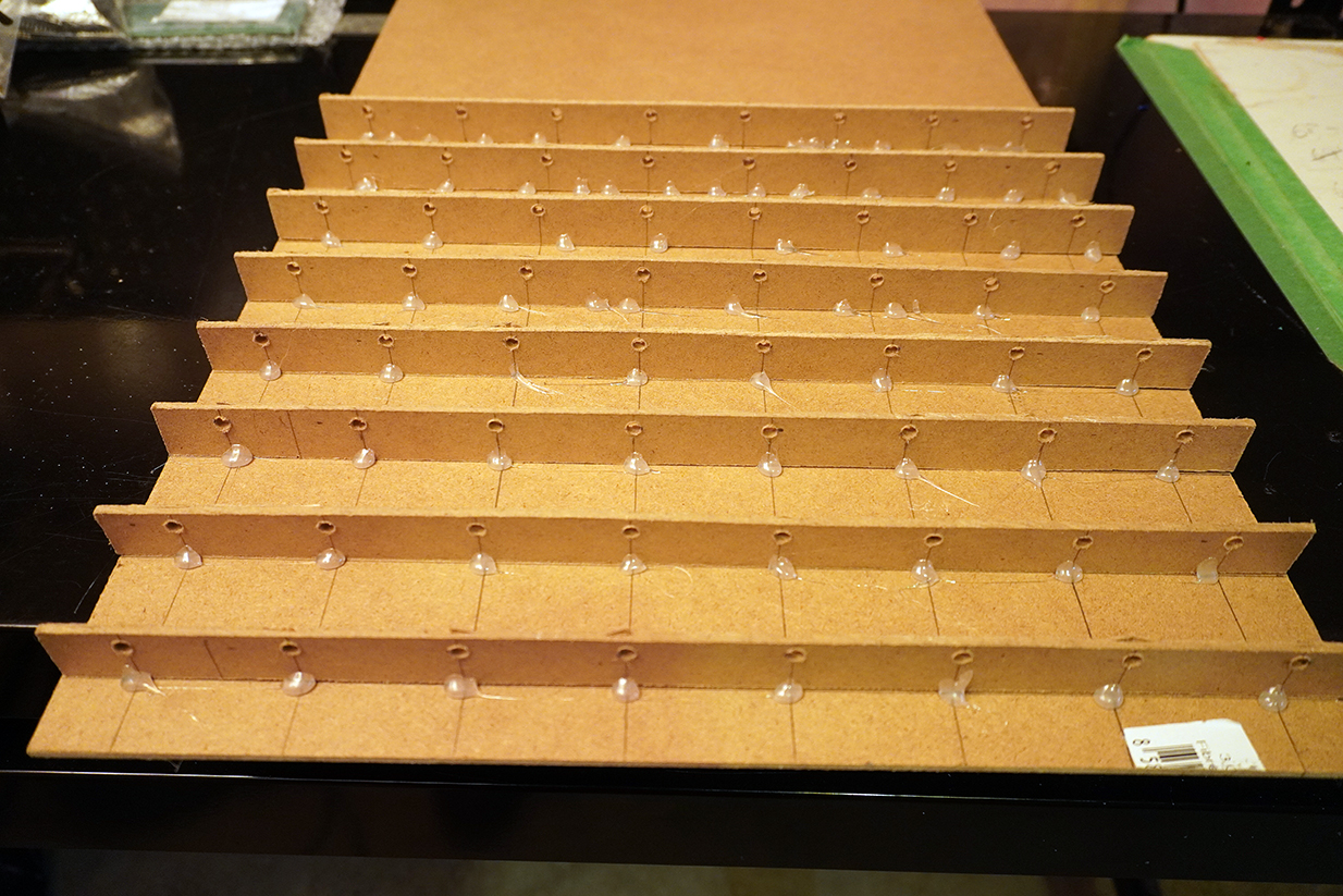
There are many different ways you can make a rack like this, I used hot glue instead of nails and it works very well. Now we are ready to place the LEDs in the holes. Notice that the anode pin is always at the bottom which later will be the layers of the cube. Once you place all the LEDs on the rack we will insert the 20 gauge steel wire in the holes of the top and bottom of the LEDs and apply solder. After that I remove the slice from the rack and insert the steel wire in the holes of the two other cathodes. This way I didn't have to make holes on the rack for the two other side cathodes.
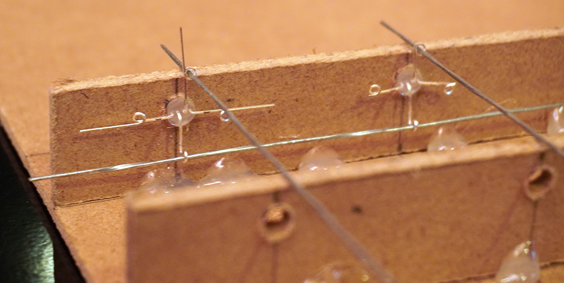
Once we have all the eight slices ready we can assembly the cube. The baseboard for the cube I used a MDF board, there are many different media you can use in this case. To make the holes on the baseboard first I measured the 2 inches and used an LED with holes like the sample bellow.
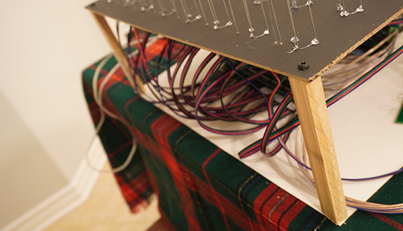
To make the holes on the board I used the Dremel tool l and after it was ready to place the slices. The board I secured on 4 small pieces of wood about 6 inches tall.
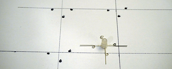
To place the leads on the holes I left long enough and I cut one end bigger than the next one so this way is easy to insert into the holes, starting from the biggest lead.
The next part 2 we are going to level up the cube, wire and connect to the circuit boards.